Introduction
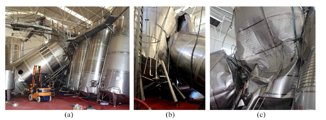
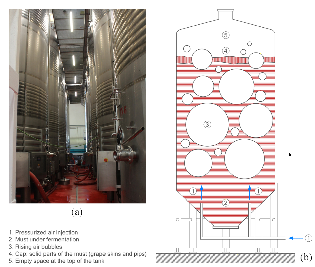
In October 2020, a 106 m³ raised stainless-steel wine tank collapsed at a winery in Alicante, Spain, triggering the progressive failure of 18 neighbouring tanks [1]. The root cause was identified as cyclic horizontal loading from a pressurized air injection system — 9 bar, 10-second pulses used during fermentation — a load case not considered in the original design.
A forensic study [1] showed the structure is adequate for vertical gravity loads, with columns at approximately 30% of yield, but critically vulnerable to horizontal actions, with horizontal ties reaching yield at only 35 mm of lateral displacement. This study extends that finding with a nonlinear FEA in Abaqus Standard, applying the equivalent static seismic force for Alicante to quantify the seismic vulnerability and compare the predicted failure with the documented collapse.
Reference Study and Failure Description
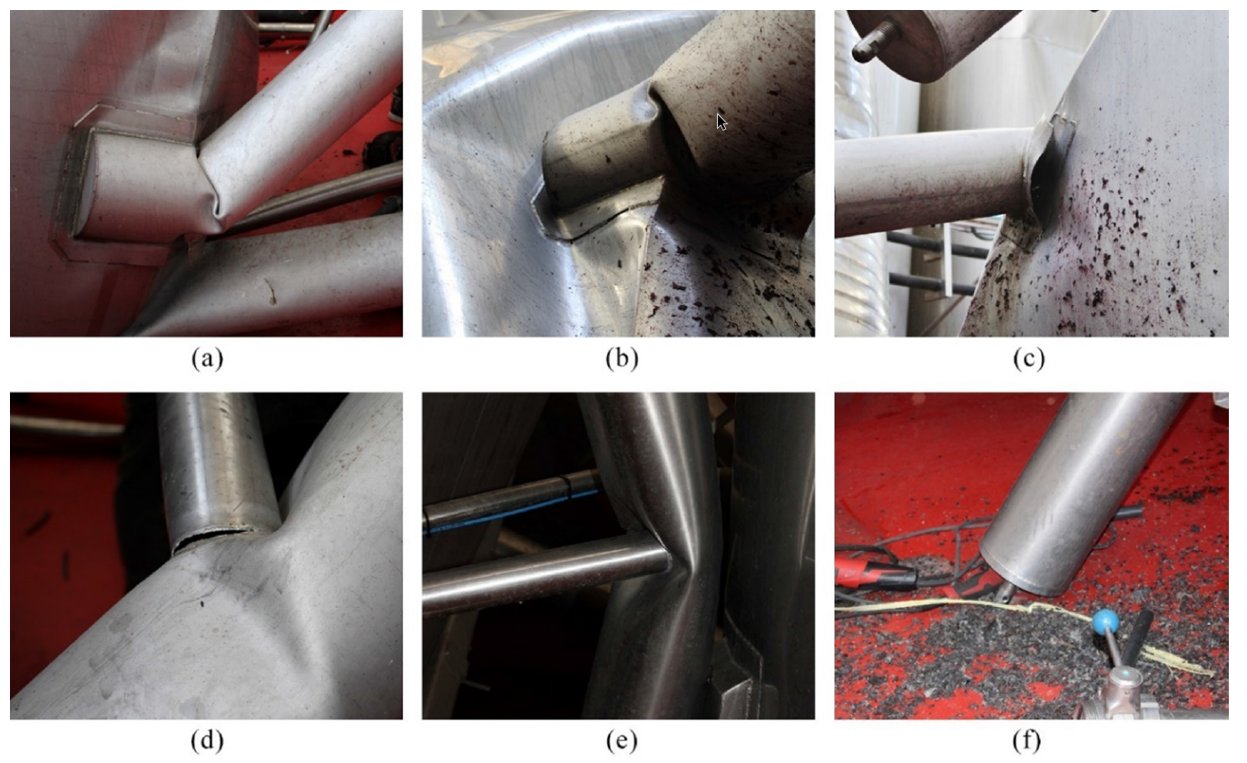
The forensic analysis by Ivorra et al. [1] documented the collapse of a tank at 85% capacity. Damage concentrated at column-tank junctions and column-brace connections: buckled column sections, broken weld lines, and fractured bracing plates. Column bases, simply supported without anchoring, remained undamaged.
Experimental testing confirmed AISI-304 material properties (yield 301–322 MPa, UTS 649–707 MPa) with ductile fracture surfaces and no evidence of fatigue, brittle fracture, or corrosion. Material deficiency and weld quality were conclusively ruled out as contributing factors.
Geometry and Dimensions
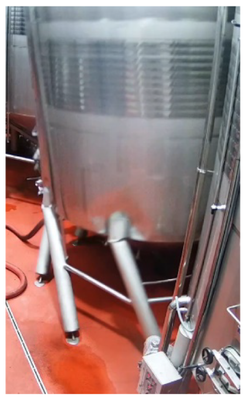
The tank geometry follows [1]: a 4200 mm diameter cylindrical vessel (4 mm wall, 10,300 mm total height) with upper and lower conical sections, supported on eight hollow columns (∅270.3 mm, 3 mm wall, 2650 mm tall) braced by seven horizontal ties (∅83.2 mm, 2 mm wall) at 1400 mm above the floor.
Material Properties
True stress–strain plasticity curves derived from experimental coupon data [1] were assigned as rate-independent plasticity models. AISI-304 (E = 200,000 MPa, ν = 0.3, σy = 304–322 MPa, UTS 649–707 MPa) was used for the tank shell and columns; AISI-316 for the upper conical section. The horizontal ties were assigned σy = 395–399 MPa, equivalent to S355 structural steel. Wine was modelled as hydrostatic pressure at 85% fill (ρ = 1000 kg/m³).
Seismic Demand
The design lateral acceleration was derived per NCSE-02 [2] and EN 1998-1 [3]. Alicante has a basic seismic acceleration ab = 0.11g (475-year return period). Accounting for an importance factor of 1.3 (failure causes major economic loss), a soil factor of 1.0 for stiff ground, and a dynamic amplification factor of 2.0 for the support legs, the resulting design lateral acceleration is 0.28g.
This 0.28g value serves as the benchmark against which the structural capacity findings are assessed. All FEA results are compared directly to this code-defined seismic demand.
FEA Model Setup
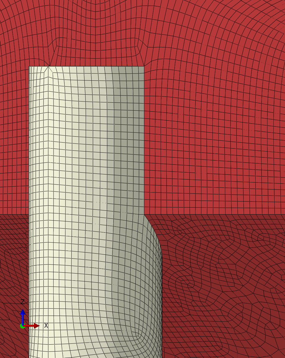
The model was built in Abaqus/Standard [4] with a dynamic implicit solver and large deformation (NLGEOM) enabled. Approximately 280,000 S4R shell elements — 4-node, reduced integration with hourglass control — were used throughout, with mesh refinement at the column-tank junctions, column-brace connections, and the lower conical section.
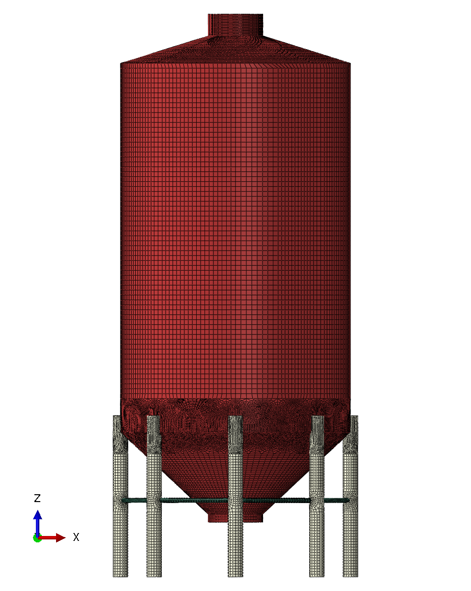
Loading was applied in two steps. Step 1 applied gravity on the full structure plus hydrostatic pressure on interior tank surfaces at 85% fill. Step 2 applied lateral surface traction on the cylindrical shell corresponding to 0.28g. Column bases were pinned — translations restrained, rotations free — consistent with the unanchored configuration observed in the physical failure. Column-to-tank and tie-to-column connections were modelled as tied constraints representing the continuous fillet welds.
Results
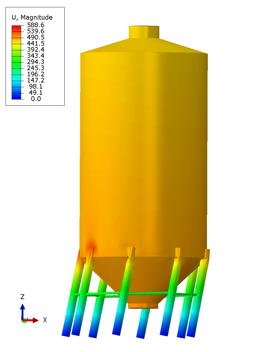
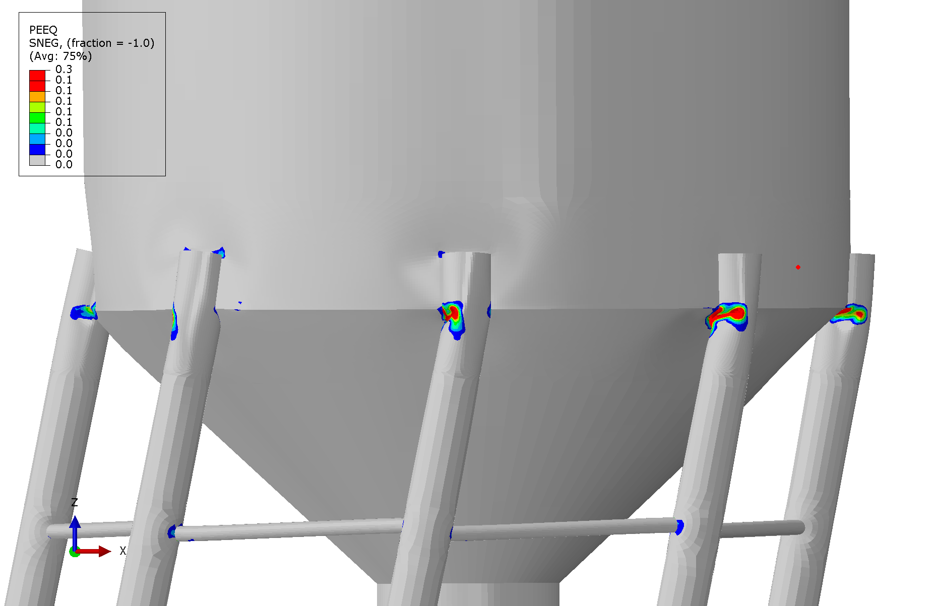
The deformed shape at 0.28g shows characteristic lateral sway with maximum column deformation at the tank junctions on the loaded side. Peak von Mises stresses of approximately 609 MPa occur at the column-brace junctions, approaching the material's ultimate tensile strength. Widespread yielding between 200–350 MPa is present throughout the support structure.
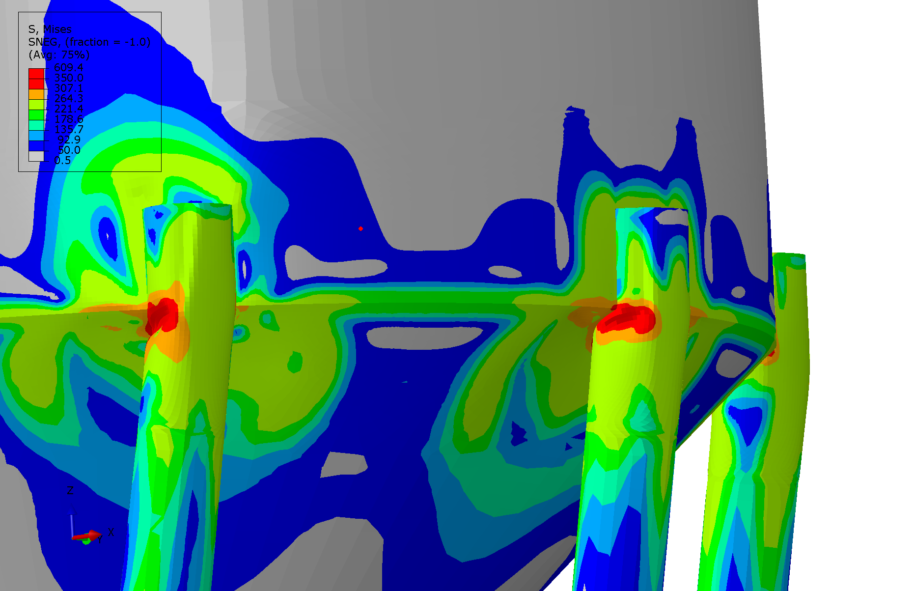
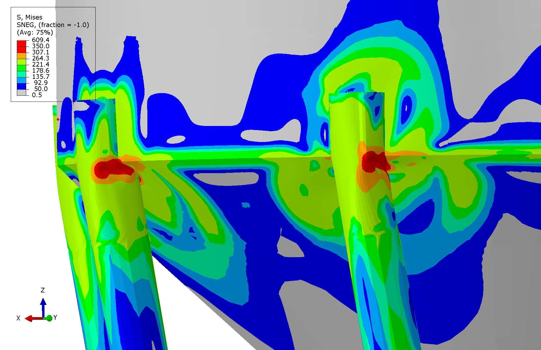
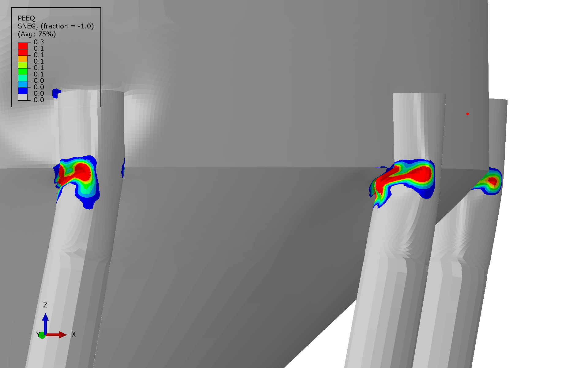
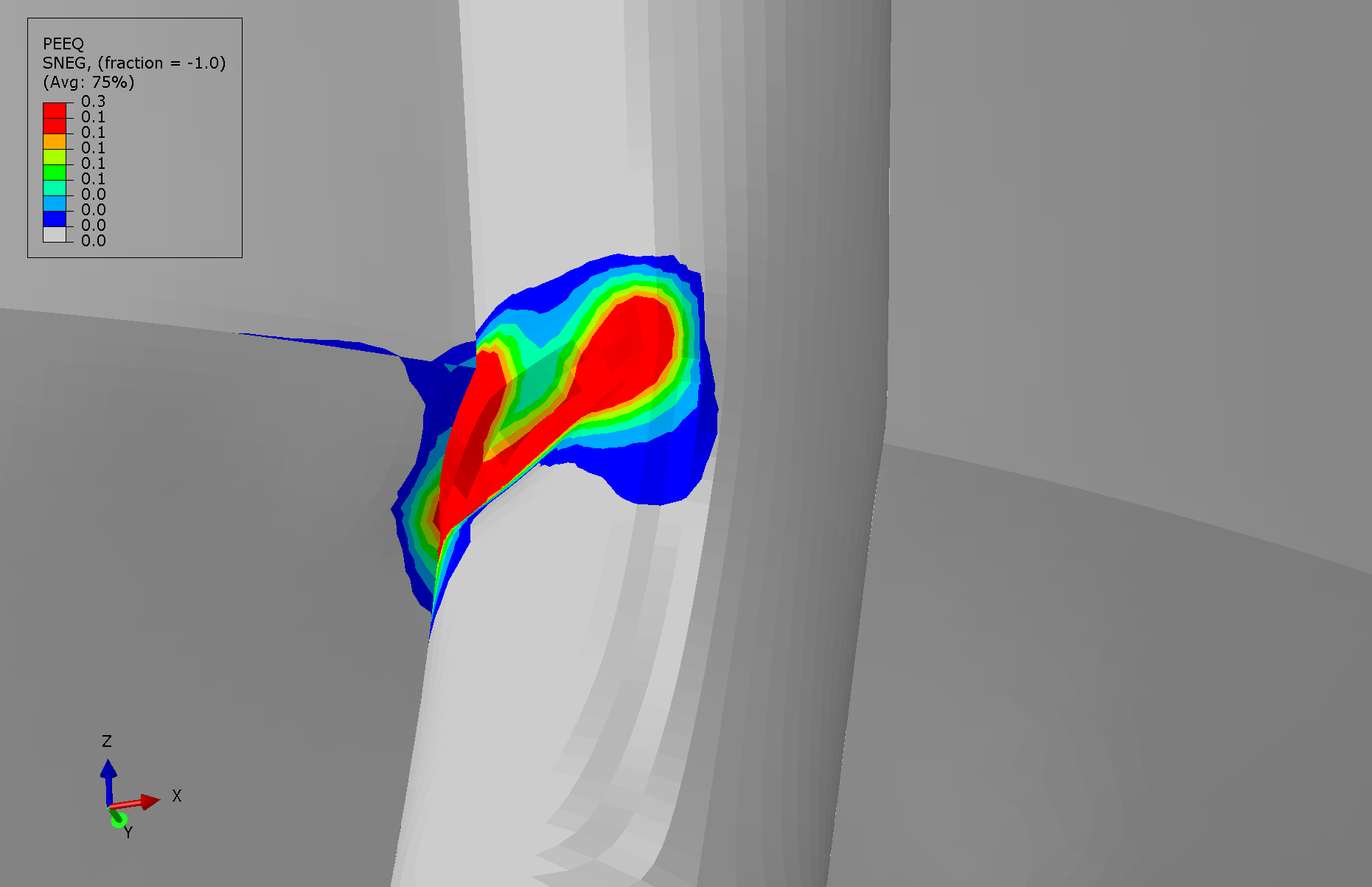
Maximum equivalent plastic strain (PEEQ) of 0.3 — equivalent to 30% permanent plastic deformation — at the column-brace connections confirms severe plastic deformation and fully developed plastic hinges. Column buckling initiates at a critical acceleration of approximately 0.04g, which is only 14% of the design seismic acceleration of 0.28g for Alicante, and 36% of the basic ground acceleration.
Comparison: FEA vs. Physical Failure
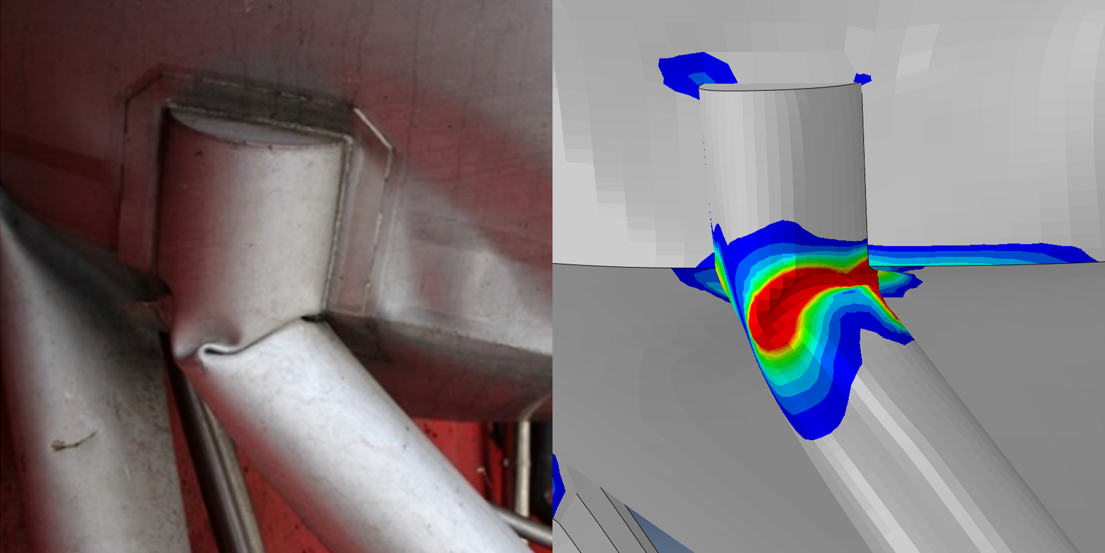
The predicted failure mode and location show excellent agreement with the documented collapse. Both the analysis and the physical evidence show column buckling initiating at the brace connection points, with plastic hinges propagating into the column walls. The side-by-side comparisons below confirm the correlation in deformation pattern, buckling shape, and damage extent.
Conclusions
The tank support structure buckles at only 0.04g — seven times lower than the NCSE-02 design seismic acceleration of 0.28g for Alicante. The predicted failure mode, column buckling at brace connections, matches the physical collapse with excellent correlation in location and deformation pattern. Under the full design seismic load, maximum equivalent plastic strain reaches 0.3, confirming severe irrecoverable damage. This structural typology is fundamentally vulnerable to any horizontal loading, and diagonal bracing is recommended to improve lateral robustness and provide alternative load paths.
References
[1] S. Ivorra, B. Torres, L. Estevan, J.M. Piqueras, Failure analysis of the collapse of a raised steel wine tank, Engineering Failure Analysis, Vol. 142, 106767, 2022.
[2] NCSE-02, Norma de Construcción Sismorresistente: Parte General y Edificación, Real Decreto 997/2002, Ministerio de Fomento, Spain, 2002.
[3] EN 1998-1:2004, Eurocode 8: Design of Structures for Earthquake Resistance — Part 1, CEN, 2004.
[4] Dassault Systèmes, Abaqus Analysis User's Manual, Version 2024.